Reference Architecture as a Code
Contents
Many shapes of Architecture
According to the wise people, an architecture is the shared understanding that the expert developers/system builders/maintainers have of the system design. It’s purpose is to maximize the probability that the decisions you have to make early in a project are the right ones. It is sort of a blueprint for the future system and captures parts, relations, boundaries, constraints.
In our business (we build and run environments and solutions for eCommerce, data management and other business activities of our customers), an important subtype of architecture is Reference Architecture. It is an architecture that serves both as a capture of best practices for a particular business case as well as a living, evolving template for creating new instances of that type of an environment. Both best practice as well as evolving features are important: the reference architecture (RA) serves as knowledge gathering in the ever changing world of cloud. As new features of AWS or Azure come, the RA needs to absorb them to incorporate latest advances and to use the best price / performance options available.
Architecture can take many physical forms. Traditionally, back in the waterfall age, it used to be a long Word document, a collection of Visio drawings or combination of both. Eventually Word was replaced by Google Docs and/or Confluence, but the same idea stayed: the prose written for humans that use manual processes to transform the prose to instances of a system, usually using cloud management console or some other tool. With the arrival of Cloudformation and Terraform, the manual process got scripted which helped repeatability during the environment creation phase, but it also introduced a new challenge: a gap between code living in version control and documentation living in a Wiki. These two separate representations of the same idea were stored in different places, requiring different tools and different credentials - despite being managed and worked on by the same people. As a natural consequence, the documentation often got out of sync with the code and instead of making understanding better and explaining / documenting, it added confusion and stopped being useful.
Some people say the special dedicated tools that hold both are the answer. Such a tool would provide a single place to hold all the information, allow creating diagrams, add documentation and maintain or generate the code. I am a bit sceptical when it comes to these kinds of solutions. I have seen good partial solution in the past (e.g. Enterprise Architect) that were delivering value, but they were limited to subset of languages and notations - e.g. UML diagrams and Java/C++ or object oriented languages. I am not aware of any tool I would consider full scale replacement for good documentation plus code. Some are promising - e.g. Cloudcraft plugin from Anton Babenko. I imagine this can be an excellent option for a startup or small company, but does not allow us enough flexibility to fit within existing tools and backend systems we have.
Rest of this blog entry will describe one possible way we are trying to overcome the documentation / code gap by using open standards, opensource tools and adhering to documentation as a code philosophy.
As a result, we define Reference Architecture as code artifact - repository that contains both executable description (Terraform Code) as well as all the documentation explaining decisions, options and alternatives using best practices such as WAF, adapted to company and customers special needs - e.g. enforcing / standardising naming, tagging, policies and in general capturing knowledge about the system built.
Selecting the format
The documentation format should satisfy these requirements
- must be file oriented (not living in database) => it can goes with terraform code to same repo
- must be Git friendly = allow good versioning and comparison
- must be easy to work with for developers
- must be expressive enough to allow formatting for pleasant Web reading experience (unlike e.g. man or pod)
- must allow easy way to generate documentation for set of interconnected pages
- must be open, well supported with good ecosystem for tools and automation
- must be CI/CD friendly (using pipelines in Bitbucket/GitHub/Gitlab)
We have ended up with a shortlist of three main contenders:
- MarkDown with MkDocs / Material Theme
- AsciiDoc
- RestructuredText with Sphinx
After evaluating each (details of this evaluation will be published in a separate post) we ended up selecting the MarkDown.
The main three reasons why we ended up selecting MarkDown were:
- familiarity - Markdown is best known format, zero learning curve
- MkDocs is Python based and with Material Theme competes very well with Sphinx generated sites
- extensibility - using Macros module allowed to solve the file include problem
Reference Architecture with Markdown and MkDocs
To add the documentation-as-a-code to the Terraform repo (the actual code), there is very little to do. Absolute necessary are only two files:
./mkdocs.yml- defines the structure of the navigation and MkDocs configuration./docs/index.md- default directory and one Markdown file (the name can me different than index.md)
It is usually a good idea to add requirements.txt file for those users who prefer to install MkDocs locally and a shell script
that runs MkDocs in Docker to the root:
docker run --rm -it -p 8000:8000 -v $(pwd):/docs miroadamy/mkdocs-material $@
and requirements.txt
mkdocs
mkdocs-material
mkdocs-minify-plugin>=0.2
mkdocs-git-revision-date-localized-plugin>=0.4
mkdocs-awesome-pages-plugin>=2.2.1
mkdocs-macros-plugin
diagrams
The last dependency is optional - only if you plan to use a Python based diagramming tool later on.
The above structure is for the documentation. The Terraform code lives in folders that are dedicated to environments or variants of environments. The general structure of the Terraform code is:
./ - PROD = named environment
   - UAT  = named environment
   - UAT-HA = named variant
   - DEVQA = named environment
   - modules/
        - database/ - local module for RDS provisioning
        - vpn/      - local module
   - examples/
        - minimal/ = example of a minimal environment
        - everything = the HA top environment example
        - typical/ = example of most common use case
        - typical-mysql = example specific to a particular database
We use three kind of Terraform modules:
* platform library
* community modules
* local RA specific modules
The most useful are Platform Library modules. These are internal, mostly closed source modules that provide packaged templates for making sure that environments we build for our customers contain all necessary security a best practices features from the ground up. For example, proper and consistent tagging of the resources is crucial for proper monitoring and cost reporting, policies are super important for security, logs processing for integration with the monitoring tools CloudOps team uses and general structure, default variables and locals to make sure that the account works well inside our AWS organization hierarchy and Pivotree workflow.
Platform library is maintained by dedicated internal team and while it is pretty comprehensive, it does not cover everything. We often adapt community modules, add our own extensions / bug fixes / documentation and republish the fork as opensource back to the community.
The local RA modules often are “second degree modules” - the modules that are using other modules. We use them for making sure there is good balance between consistency among environments and respecting the DRY (don’t repeat yourself) design principle.
Each of the Terraform folders for environment, module or example can have it’s own docs/ subfolder
where the environment/module/example specific information can reside. The main navigation can easily point to these
pages and provide a consistent, global documentation tree.
The key feature for good user experience is ability to include both Markdown fragments and code files into the compiled
documentation - this is provided by include macro added in the mkdocs.yml combined with a “proxy” markdown files that
have the name of the environment/module or example they represent and simply include the main Markdown file for that environment
The file for production environment - ./docs/PROD.md (the terraform code for production is in the ./PROD/ folder)
{% include 'PROD/docs/README.md' %}
Here is an example - a starter template how such architecture can look like
Just the documentation portion:
➜  aaac-starter-template tree
.
├── CHANGELOG.md
├── DEV
│   └── docs
│       └── README.md
├── PROD
│   └── docs
│       └── README.md
├── README.md
├── UAT
│   └── docs
│       └── README.md
├── docs
│   ├── DEV.md
│   ├── PROD.md
│   ├── UAT.md
│   ├── example-everything.md
│   ├── example-minimal.md
│   ├── example-typical.md
│   ├── index.md
│   ├── mkdocs
│   │   ├── about.md
│   │   ├── macros-demo1.md
│   │   ├── markdown-demo.md
│   │   └── snippet.md
│   ├── module-demo-1.md
│   └── module-demo-2.md
├── document_server.sh
├── examples
│   ├── everything
│   │   └── README.md
│   ├── minimal
│   │   └── README.md
│   └── typical
│       └── README.md
├── mkdocs.yml
├── modules
│   ├── demo-1
│   │   └── docs
│   │       └── README.md
│   └── demo-2
│       └── docs
│           └── README.md
└── requirements.txt

17 directories, 26 files
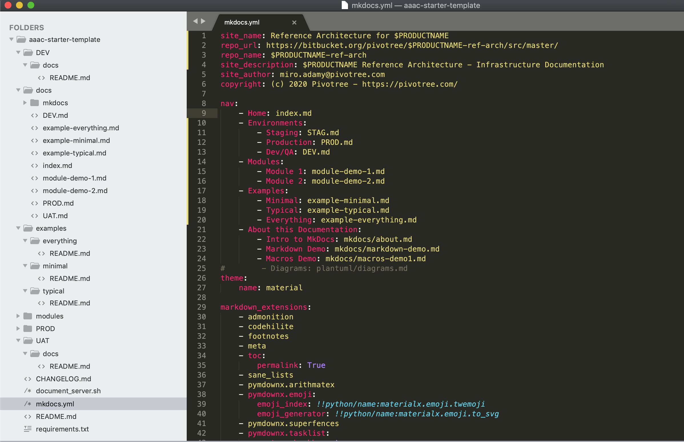
This is how the navigation in the table of content looks like in the source form:
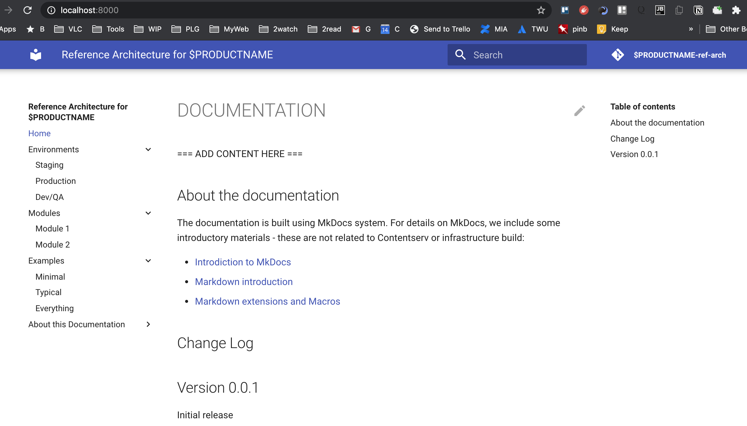
and the rendered form:
Terraform code organization
This topic deserves deeper discussion, but at the high level, Terraform does not care how many files is there in the “project”
(which must be located in single directory), what are the file names (as long as they have .tf extension)
or how is the content distributed among them.
We are using our own adopted version of a naming/content allocation scheme for Terraform files that looks looks like this (this is an example that uses Platform library and most of the files are “clients” of some module):
- main.tf - the main functionality
- providers.tf - configuration of the AWS provider (locked version) and others
- version.tf - lock terraform version
- outputs.tf - all output produced
- variables.tf - declaration of all variables without default values
- pivotree-variables.tf - company-specific variables used for integration across sales, app services and ops
- locals.tf - the local definition - mainly for consistent tagging
- init.auto.tfvars - the predefined values of the variables with comments
- security-groups.tf - explicit definition of all used SG
- (optional) AWS-RESOURCE.net - depending on module, additional files for AWS resources (ELB, RDS, EC2 etc)
- docs/README.md or README.md - local documentation for this set of files only
Here is an example of the Reference architecture repository with one module, one example and DEV environment containing the code for Terraform:
.
├── CHANGELOG.md
├── DEV
│   ├── docs
│   │   └── README.md
│   ├── init.auto.tfvars
│   ├── locals.tf
│   ├── main.tf
│   ├── outputs.tf
│   ├── pivotree-variables.tf
│   ├── providers.tf
│   ├── security-groups.tf
│   ├── variables.tf
│   ├── version.tf
│   └── vpc-net.tf
├── PROD
│   └── docs
│       └── README.md
├── README.md
├── UAT
│   └── docs
│       └── README.md
├── docs
│   ├── DEV.md
│   ├── PROD.md
│   ├── UAT.md
│   ├── example-everything.md
│   ├── example-minimal.md
│   ├── example-typical.md
│   ├── index.md
│   ├── mkdocs
│   │   ├── about.md
│   │   ├── macros-demo1.md
│   │   ├── markdown-demo.md
│   │   └── snippet.md
│   ├── module-demo-1.md
│   └── module-demo-2.md
├── document_server.sh
├── examples
│   ├── everything
│   │   └── README.md
│   ├── minimal
│   │   └── README.md
│   └── typical
│       ├── README.md
│       ├── init.auto.tfvars
│       ├── locals.tf
│       ├── main.tf
│       ├── outputs.tf
│       ├── pivotree-variables.tf
│       ├── providers.tf
│       ├── security-groups.tf
│       ├── variables.tf
│       ├── version.tf
│       └── vpc-net.tf
├── mkdocs.yml
├── modules
│   ├── demo-1
│   │   ├── docs
│   │   │   └── README.md
│   │   ├── init.auto.tfvars
│   │   ├── locals.tf
│   │   ├── main.tf
│   │   ├── outputs.tf
│   │   ├── pivotree-variables.tf
│   │   ├── providers.tf
│   │   ├── security-groups.tf
│   │   ├── variables.tf
│   │   ├── version.tf
│   │   └── vpc-net.tf
│   └── demo-2
│       └── docs
│           └── README.md
└── requirements.txt

17 directories, 56 files
Repository layout - or what belongs where
At this stage, we have quite a few folders or locations, both for the documentation as well as for the Terraform source code, so the natural question is: what should be placed where.
There are several ways how to address this, but the most important rule that should be kept in mind is:
- pick ONE strategy that works for your process/way of thinking
- document it
- stick to it
Here is what we are currently at:
First: modules. This folder is often empty and when it is not empty, it should contain internal modules. These are reusable
ways how to build part of the solution from other modules (public or private) or from resources. These are potential incubators for
the new library modules. It is very important to pay attention to variables and outputs of the module, as these will determine its
usability.
The documentation of the module should focus on details about variables (module parameters) and module outputs, default values as well as contain examples of what gets built.
Next: examples. This is the core of Architecture as a Code - both on code as well as on documentation side. If there are
variants of the architecture, there should be examples for each. An example is like a build for a non-existing project or a
fictional customer. Examples should have good names and their documentation should describe the use case and decision criteria
when the example is a good solution. At minimum, there should be 3 examples, named minimal, everything and typical.
If the architecture repository contains internal modules, there should be enough examples for each module.
Last - the environment folders - UAT, PROD, DEV - should contain adapted examples of the build for a particular project.
These are (from architecture point of view) transient folders as they will “grow and die” many times during the architecture lifecycle.
Reference Architecture Lifecycle
The main purpose of reference architecture is to support reuse and consistency between repetitive builds of the environments, while providing an easier way to extract changes, updates and best practices related to environment/cloud and tools evolution.
The simplest approach is to start a new build with a detached copy of the latest version of a RA repository. This is very easy and fast but makes later consolidation harder and usually results in consolidation never happens. At the end, there is set of snowflake repositories with no easy way to compare them or see their evolution path.
Better approach is using 2 repositories: a Project repository and an Architecture repo.
Start with shallow cloning of the Architecture repository using architecture as origin name:
git clone --depth=1 --origin architecture ARCHITECTURE_REPO_URL
Then create empty repository for the project in the Bitbucket/Github/Gitlab and add it as remote repository to the architecture clone:
git remote add origin PROJECT_REPO_URL
The starting point of the new environments will be the current (develop) state of the architecture repo. Let’s assume the project name
is RA_DEMO.
We will be working with multiple local branches that will be synchronized with the remote branches in these two repositories:
develop => origin/develop - environment definition in progress
master  => origin/master  - environment release state
RA_DEMO => architecture/PROJECTS/RA_DEMO
To set it up:
git checkout master
git push -u origin/master

git checkout -b develop
git merge archirecture/develop
git push -u origin/develop

git checkout -b RA_DEMO
git push -u architecture/PROJECTS/RA_DEMO
Main work will be happening in the develop branch, pushing the changes to origin/develop.
This means creating folders for ENV, adding Terraform code and documentation, testing documentation locally, running the code and adjusting.
When the environment and documentation reaches tested state, we merge to master and push to project repository, where (eventually) the CI/DC pipelines will run and deploy the infrastructure.
Important thing to keep in mind is avoiding reformatting and large content re-arrangement which would complicate the next phase.
When the environment is ready, we may end up with some changes or additions under ./modules or ./examples that are worthy of keeping as
part of next builds based on this reference architecture. This is where the reintegration step comes into place.
Reintegration - project side
The goal of this phase is to make sure that worthy additions and improvements will be kept for the future builds.
It starts all by switching to RA_DEMO branch and merging the state we need to integrate:
git checkout RA_DEMO
git merge master
Usually, the details of the build environment are of little interest for the architecture. We can remove the ENV folders, add more
documentation or better details while working on the RA_DEMO branch, producing one or more commits on this branch. All this commit
should be local commits - do NOT push to architecture yet. Sometimes we may want to consider making a ENV build a new example
- copy the TF code under
./examples, name it accordingly and update documentation / remove customer specific data.
Sometimes we discover issues that should be addressed on the architecture level. Adding them to backlog.md is great way that they will
be available for the maintainer of the RA repo.
When the state of the architecture is in desired state, we can squeeze the commits to single commit using interactive rebase (see this for more details)
After rebase, we can push the RA_DEMO to architecture remote:
git push
and create a pull request for Architecture repo, to merge the PROJECT/RA_DEMO to develop.
Reintegration - architecture side
Second part of the reintegration happens completely in the Architecture repo, often by different person / team.
Clone the Architecture repo, switch to newly added PROJECT/RA_DEMO branch, review the addition.
Every change should be tested and independently validated. Ideally the architecture team adds dedicated tests for the new examples and more documentation, reviews backlog.md for list of issues / improvements suggested and creates tickets based on this information.
If everything is OK, increase version of the RA and merge to develop - to make it available for next iteration.
The starter template of the reference architecture using the above approach is available at my Github
ROI consideration
Creation and maintenance of the reference architecture is a non-trivial investment of time and resource. Not always this kind of effort is warranted. From our experience, here are some decision criteria when considering standardization and using this approach:
- how many environments will be created during the next month / quarter ? RA and AaaC is less useful for small number of builds over longer periods of time
- what is the platform complexity ? For highly complex platforms with complex dependencies and long implementation cycle, it makes more sense focus on smaller building blocks rather than on full RA
- what is the speed of change for the platform ? Every major release (and often minor release as well) will require updating and re-testing the RA. For fast changing environment, this can be too expensive
- what is the customer requirements variability ? If there are huge differences between the builds, the RA will need to contain large number of examples and variants which will make maintenance and testing more costly.
The ideal candidates for the AaaC / RA DevOps cycle are small to medium sized solutions with small number of variants, with customers requirements being similar enough to fit into 3-4 cases and with large enough number of deployments for a platform version that allows good test coverage.
Diagrams Markdown Friendly Way
The traditional way how to create diagram and add them to the documentation is:
- use an external tool - either a local one (Omnigraffle, Visio) or an online tool (LucidChart, Draw.IO)
- save source of the diagram somewhere (local drive or cloud)
- export the image rendering of the diagram to some image format (e.g. PNG)
- link the image to your documentation
While this is easy and convenient way of doing things with very low barrier of entry, there are several disadvantage I’d like to point out
- one must have the same version of editing software - on a proper platform if local. The challenges of sharing Omnigrafle source with Windows users (or Visio with Linux users) are non-trivial. For online tools, one must have access / license to the software.
- the native format is not living in the same place as the documentation - unless one uses local tools (which brings platform dependency) and life cycles of the documentation and diagrams are separate. This violates the original intention of keeping lifecycle of code and documentation together, and diagrams are fundamental part of the documentation
- native format is impossible to properly version control. As a consequence of the previous point, there is no easy way to tell differences between various versions of the diagram from the source and image.
- it is very hard to automate the rendering part to get e.g. different resolutions of the images for different media
Binary Editor Alternatives
I’d like to showcase / demo two alternatives to visual GUI editors that essentially apply the same idea as Terraform to infrastructure to the process of creating diagrams. Instead of using GUI editor (~ AWS Console) you describe the intended diagram (~ infrastructure) in an open, free Domain Specific Language PlantUML (~ Terraform) and use free, opensource and readily available tools to transform the DSL to target assets - images (~ resources). This is the approach using PlantUML
PlantUML diagrams
The PlantUML is well established DSL with great ecosystem and support. It allows creating wide variety of diagrams and converting them either online or in Docker or using plugin for IDE
There is also standard library of modules including AWS and excellent guide with examples and details
Here is a quick demo of few examples what can be done with PlatUML
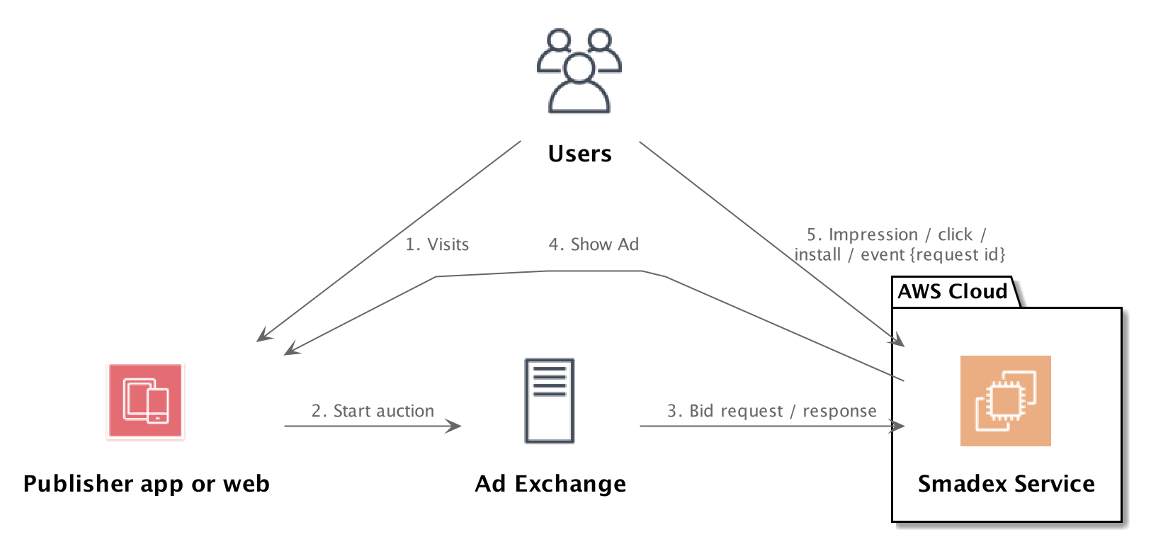
AWS with PlantUML
@startuml
!include <awslib/AWSCommon>
!include <awslib/AWSSimplified.puml>
!include <awslib/Compute/all.puml>
!include <awslib/mobile/all.puml>
!include <awslib/general/all.puml>
!include <awslib/GroupIcons/all.puml>

 skinparam linetype polyline
' skinparam linetype ortho

package "AWS Cloud" {
EC2(Smadex, "Smadex Service", " ")
}

Users(Users, "Users", " ")
TraditionalServer(AdExchange, "Ad Exchange", " ")
Mobile(Mobile, "Publisher app or web", " ")

Users -down-> Mobile: 1. Visits
Mobile -right-> AdExchange: 2. Start auction
AdExchange -right-> Smadex: 3. Bid request / response
Smadex -left-> Mobile: 4. Show Ad
Users -right-> Smadex: 5. Impression / click / install / event {request id}
@enduml
@startuml
!include <awslib/AWSCommon>
!include <awslib/AWSSimplified.puml>
!include <awslib/Compute/all.puml>
!include <awslib/mobile/all.puml>
!include <awslib/general/all.puml>
!include <awslib/GroupIcons/all.puml>
!include <awslib/Storage/all.puml>
!include <awslib/ManagementAndGovernance/all.puml>
!include <awslib/CustomerEngagement/all.puml>
!include <awslib/MachineLearning/all.puml>
!include <awslib/NetworkingAndContentDelivery/all.puml>
!include <awslib/Database/all.puml>
!include <awslib/ApplicationIntegration/all.puml>

'Compute/General
'Storage/SimpleStorageServiceS3.png
'ApplicationIntegration/SQS.png
'Compute/Lambda.png
'Compute/EC2
'ManagementAndGovernance/CloudWatch.png
'CustomerEngagement/SESEmail.png
'MachineLearning/SageMaker.png
''Mobile/APIGateway.png
'NetworkingAndContentDelivery/APIGateway2.png
'Database/Aurora.png
'ApplicationIntegration/SQSQueue.png


skinparam linetype polyline
' skinparam linetype ortho

'top left section
'-------------------------------------------------------------
package EC2_Instance {
General(IngestionApp, "Ingestion App", " ")
General(ChunkingApp, "Chunking Orchestration App", " ")
}

SimpleStorageServiceS3(S3Staging, "Amazon S3 Staging Bucket", " ")
SQS(SQSIngest, "Amazon SQS Ingest Queue", " ")

Lambda(LambdaTrigger, "AWS Lambda Trigger Function", " ")

LambdaTrigger -up-> IngestionApp
IngestionApp -up-> SQSIngest
SQSIngest -down-> ChunkingApp
S3Staging <-down-> EC2_Instance

'top right section
'-------------------------------------------------------------
together {
SQS(SQSLargeFileQueue, "Amazon SQS Large File Queue", " ")
SQS(SQSSmallFileQueue, "Amazon SQS Small File Queue", " ")
SQS(SQSSingleFileQueue, "Amazon SQS Single File Queue", " ")

EC2(LargeFileChunkingAppEC2, "Large File Chunking App on EC2", " ")
Lambda(LambdaSmallFileChunking, "Small File Chunking Lambda", " ")
Lambda(ImageConversionLambdaFunction, "Image Conversion Lambda Function", " ")
}
'todo dashed line boundary
package DLQ {
SQSQueue(DLQ1, "DLQ", " ")
SQSQueue(DLQ2, "DLQ", " ")
SQSQueue(DLQ3, "DLQ", " ")
}

ChunkingApp -right-> SQSLargeFileQueue
ChunkingApp -right-> SQSSmallFileQueue
ChunkingApp -right-> SQSSingleFileQueue

SQSLargeFileQueue -right-> LargeFileChunkingAppEC2
LargeFileChunkingAppEC2 -down-> SQSSmallFileQueue
SQSSmallFileQueue -right-> LambdaSmallFileChunking
LambdaSmallFileChunking -down-> SQSSingleFileQueue
SQSSingleFileQueue -right-> ImageConversionLambdaFunction

'todo dashed line
SQSLargeFileQueue -down-> DLQ1
SQSSmallFileQueue -down-> DLQ2
SQSSingleFileQueue -down-> DLQ3


'bottom right section
'-------------------------------------------------------------

SimpleStorageServiceS3(S3Images, "Amazon S3 Images Bucket", " ")
EC2(EC2DLQFailsafeApp, "DLQ Failsafe App on EC2", " ")
SQS(SQSConvertedImageQueue, "Amazon SQS Converted Image Queue", " ")
Lambda(LambdaInferenceInvocation, "Inference Invocation Lambda Function", " ")
Aurora(Aurora, "Amazon Aurora", " ")
APIGateway(AmazonAPIGateway, "Amazon API Gateway", "")
SageMaker(AmazonSageMaker, "Amazon SageMaker Endpoint", "")

DLQ1 -down-> EC2DLQFailsafeApp
DLQ2 -down-> EC2DLQFailsafeApp
DLQ3 -down-> EC2DLQFailsafeApp

EC2DLQFailsafeApp -right-> S3Images

ImageConversionLambdaFunction -down-> S3Images
S3Images -down-> SQSConvertedImageQueue
SQSConvertedImageQueue -left-> LambdaInferenceInvocation
LambdaInferenceInvocation -down-> Aurora
LambdaInferenceInvocation <-left-> AmazonAPIGateway
AmazonAPIGateway <-left-> AmazonSageMaker


'bottom left section
'-------------------------------------------------------------

CloudWatch(CloudWatch, "Amazon Cloudwatch", " ")
SNS(SNS1, "Amazon SNS", "")
SESEmail(SESEmail, "Email Notification", "")

CloudWatch -right-> DLQ
CloudWatch -left-> SNS1
SNS1 -left-> SESEmail

footer %filename() rendered with PlantUML version %version()\nThe Hitchhiker’s Guide to PlantUML
@enduml
( or see the source: ) - source PUML

Workflow with PlantUML
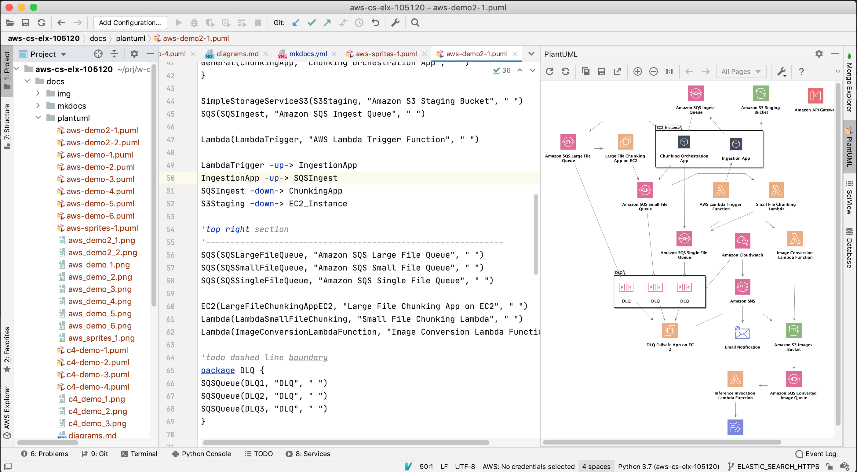
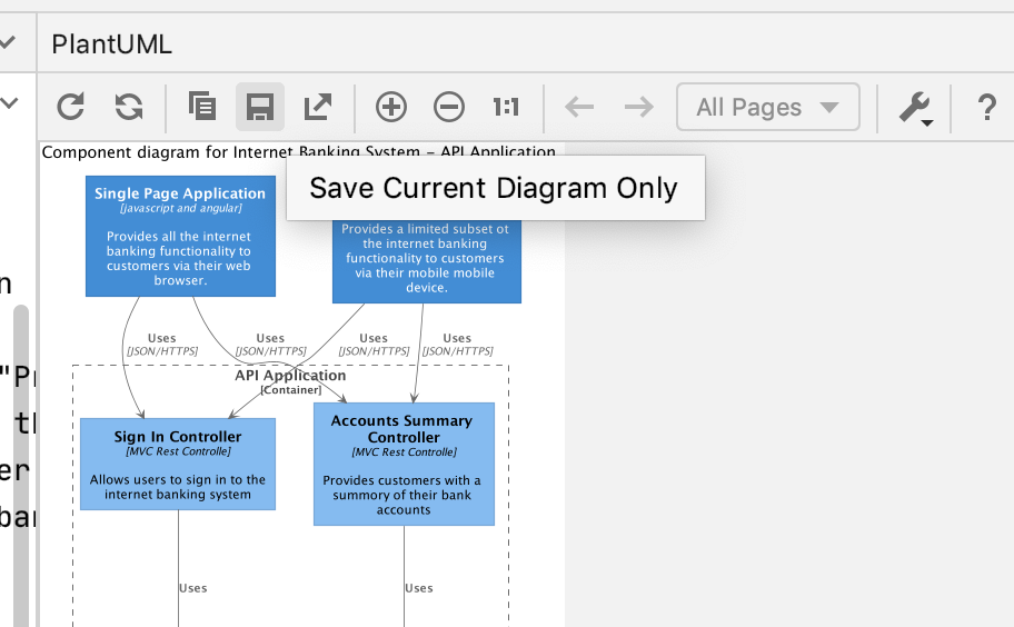
Using PlantUML for diagrams is pretty straightforward. Assuming that you have installed plugin simply add the file with PUML extension to the project. It will be recognized and PyCharm/IntelliJ will show colored syntax with preview:
After creating the desired image, use the plugin save button to generate PNG version of the diagram and add it to the project - ideally same folder as the PUML file.
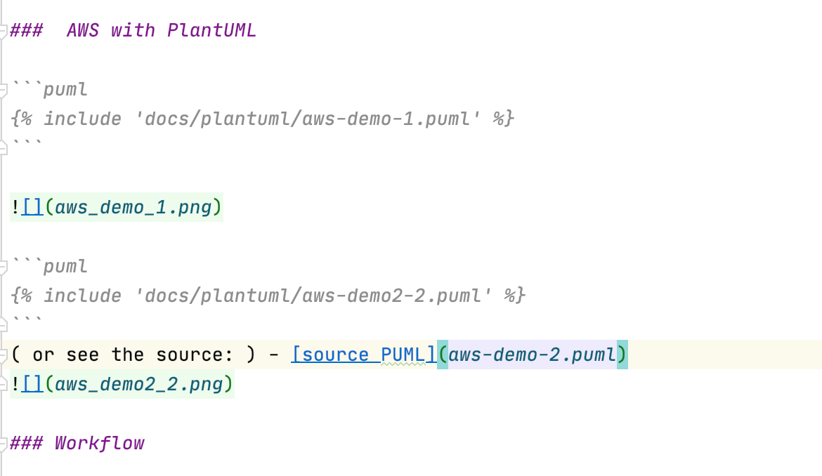
Including the sources into documentation is very simple: you can either embedd the full source or provide link to it
Pure Python as graph DSL
Recently I have discovered different approach to specifying diagrams in a source code friendly manner. There is an open source project diagrams - see also github. Good introduction to this approach is this blog.
It is elegant and beautiful.
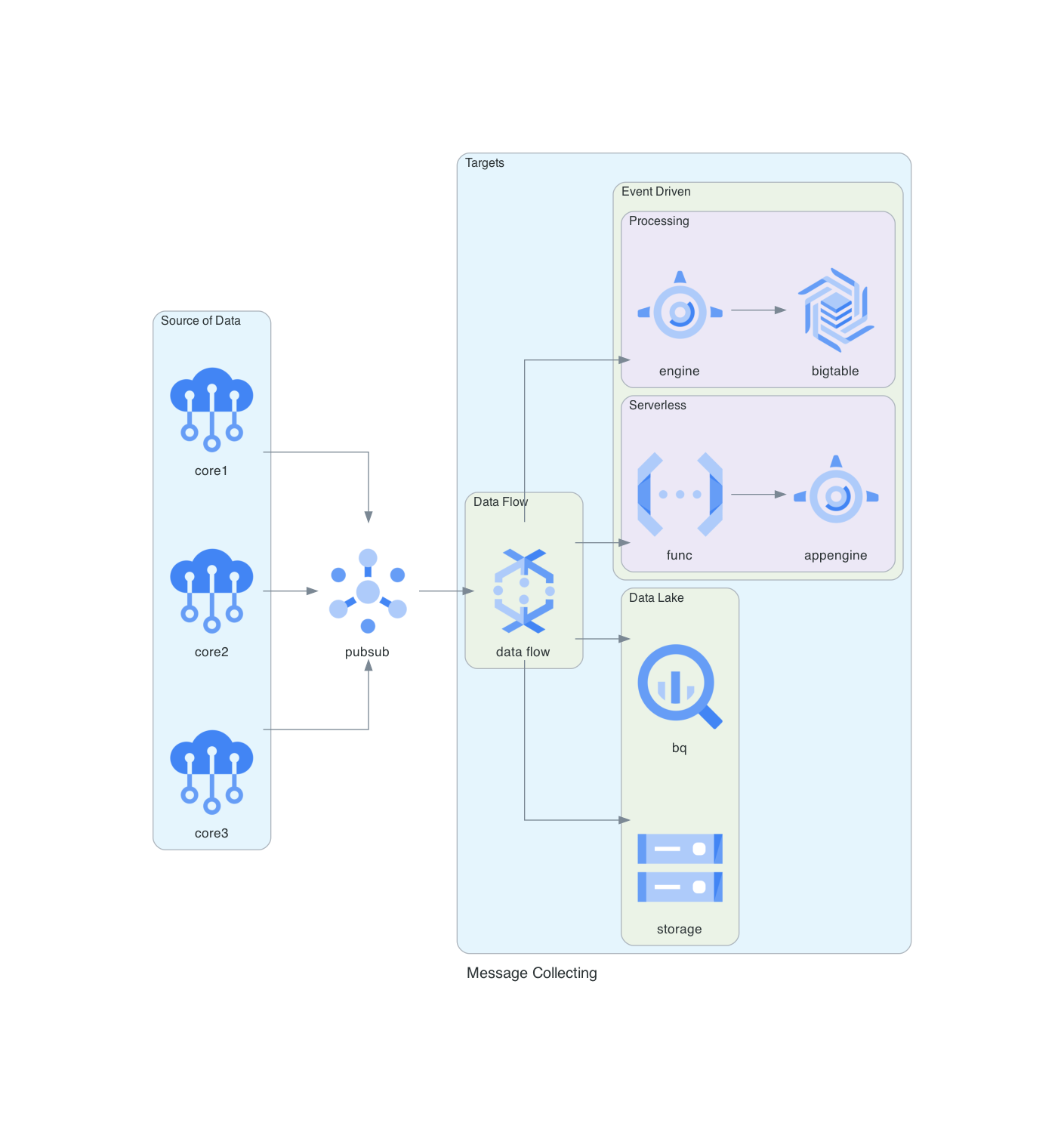
From this:
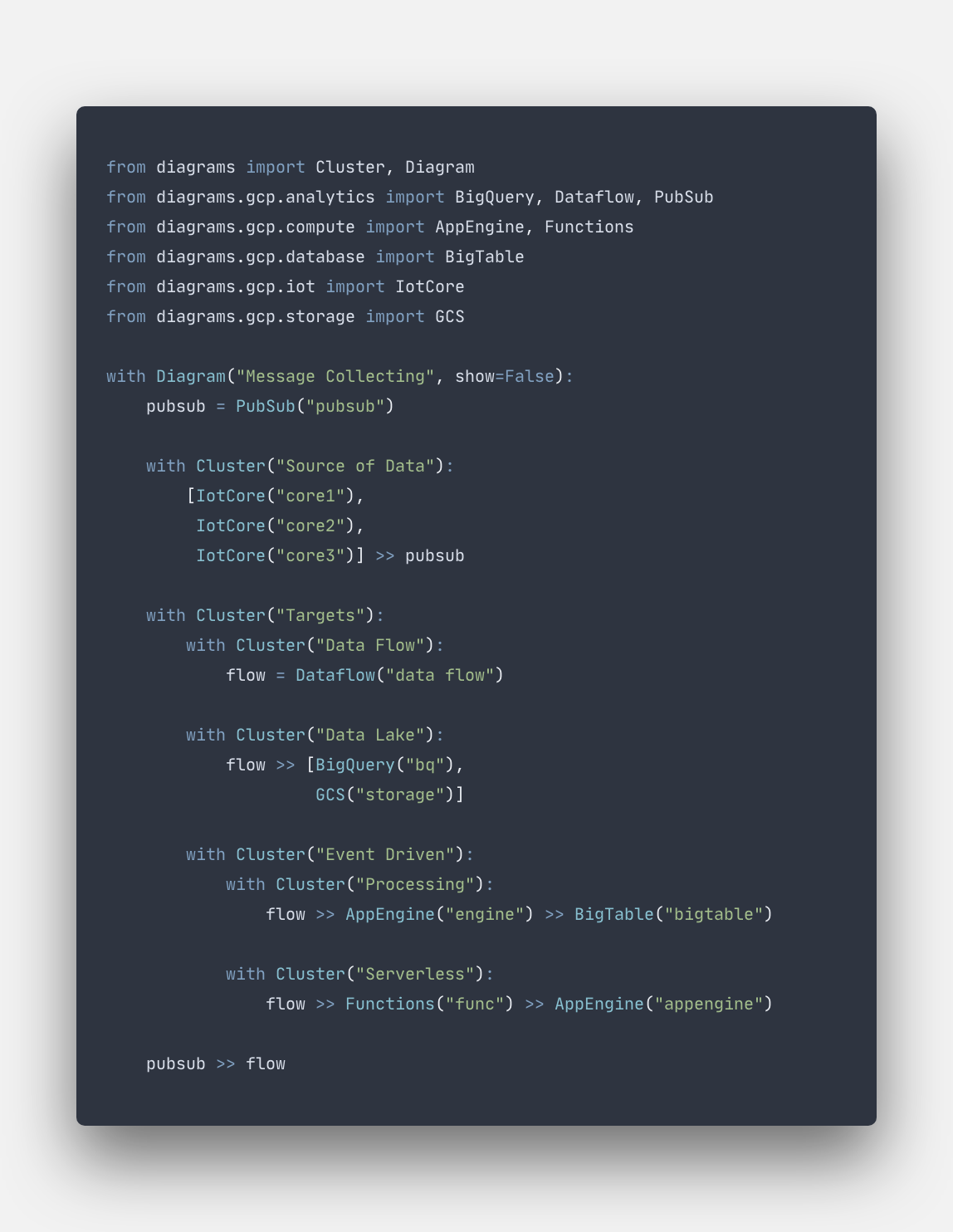
generates this
Author Miro Adamy
LastMod 2020-08-10
License (c) 2006-2020 Miro Adamy